Posts

Basic Overview of ET200 SP HA

Image
The high-performance I/O system SIMATIC ET 200SP HA – perfectly matched to the requirements of the process industry and with clear advantages wherever ruggedness and maximum availability are important in the process and manufacturing industry. Benefits Availability: Redundancy at the PROFINET interface (S2 or R1) Hot swapping during runtime station expansion possible during runtime Easy to Use: Compact modules with permanent wiring. One terminal block for all 24 V standard signals Tool-free connection system with push-in-terminals Compact Design Compact with up to 56 i/o modules per station High concentration of up to 32 channels on a module that is only 22.5 mm wide System-integrated power bus Seamless integration in SIMATIC PCS new PROFINET IO communication standard Functions Main functions Compact I/O modules Up to 32 channels on a module that is 22.5 mm wide Up to 56 modules per station Perfectly suited for applications in the field Installation up to hazardous zone 2 Extended temp...

S7-1500 Memory Concepts

Image
  Below is the memory area overview:  Load Memory Non volatile memory for User program, data blocks, technical object, recipe and data logs. We can copy additional data to load memory through a web server or explorer. An inserted Memory card is required for operating the CPU. For CPU 1518, extra load memory is required for : Linux runtime which runs in parallel with CPU runtime C/C++ runtime application CPU function libraries. Linux runtime is the environment required for execution of a runtime application and CPU runtime is required for applications requiring CPU runtime application. Work Memory Work memory contains executable code and data blocks. It is integrated in the CPU and cannot be extended. For CPU 1528-4PN/DP additional work memory is required for CPU function libraries and C/C++ runtime applications. Retentive Memory It is a non volatile memory for saving limited amount of data in case of power failure. It can be deleted with memory reset or reset to factory settin...

Basics Of PROFINET Redundancy

Image
  Overview Of PROFINET system redundancy PROFINET system redundancy standard distinguishes between four configurations with the designation NAP S1,S2,R1 and R2. NAP: Network Access Point means PN interface of Module. It is not the interface IO module but PROFINET Port on the module. If a module has 2 ports acting as a switch then it is counted as 1 NAP. The S (Single) describes and IO device with one PN interface. An R (Redundant) indicates that the IO device has two NAPs: Either 2 interface module each with a PN interface or One interface module with two independent PN interface.  With NAP S2 and Rs, two IO controllers(IOCs) can be assigned to one NAP-a PN interface of an interface of an interface module. It should be noted here that the NAP in operation uses only one of the two connections actively for IO data exchange and switched to the other connection only if there is a failure. Important Note: With system redundancy, the IO controller (IOC) – in other words the PN inter...

Firmware Update of S7-1500 CPU/interface module, display and I/O modules.

Image
Update the firmware of the CPU/interface module, display and the I/O modules using firmware files. The retentive data is retained after the execution of the firmware update.  Options for Firmware Update Online in Step7 via Online and Diagnostics Online in Step7 via accessible devices (Profinet) Via Simatic memory card. Via integrated web server Online via the Simatic automation tool. Step 7 via Online and Diagnostics Open "Online and Diagnostic" option . Select Firmware update option under "Function". For CPU you can select display or CPU. screenshot as below: Click the "Browse" button to select the firmware update files in the "Firmware update"  area. Select the matching firmware file. The table in the firmware update area lists all modules  for which an update is possible with the selected firmware file.  Click the "Run update" button. If the module can interpret the selected file, the file is  downloaded to the module. If you must ch...

Replacing the Display/Front Cover of S7-1500 PLC

Image
 Replace Display of Standard, F-CPU/Compact CPU The display is pluggable. You can remove or replace the display during operation (RUN). Removing or replacing the display does not have any influence on the running CPU. To remove the display from the CPU, follow these steps:  1. Flip the front cover up.  2. Press with a 3.5 mm screwdriver from the front into the unlatching mechanism of the      display. This is found in the middle directly above the display.  3. Press the screwdriver lightly from above and lever out the display from the support.  4. Remove the display in an upward direction.  5. You have removed the display.  6. Place the new display in the CPU and press the display firmly in the top area until it      audibly engages.  7. Flip the front cover down into place. 

Identification and Maintenance Data for S7-1500

 Identification and Maintenance data is information saved on module. The data is Read-only (I data) Readable/writable (M data) Options for reading out I&M data Via the user program Using the display of CPU Via Step7 or HMI device Via the CPU web server. Reading I&M data from displays To read I&M data of centrally used module: On CPU display select Modules menu Select the menu command "local modules" and confirm "OK" Select the slot of module and confirm with "OK" To read I&M data of module used in distributed mode On CPU display select Modules menu. Select the corresponding distributed I/O system and confirm with "OK"  Select the slot of module and confirm with "OK" Reading I&M data via Step7 In project tree, select the CPU/interface module Go to "Online and Diagnostic" In the "Diagnostic" folder, select the "General" area. We can enter maintenance data like plant designation, location i...

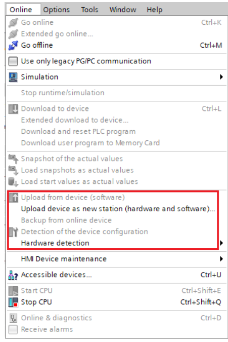
Project upload option available in TIA.

Image
 Project Upload It might happen that TIA project Downloaded version in PLC is different from the available software so there are various option to upload the project. Options depends on the available version. Below legends will help you understand the table where feasibility of various upload options is possible. In below pics you can understand that what are the available options when you have a particular version and program downloaded in PLC is from different version.  

Project Migration in TIA from Older version to TIA V17

Image
  TIA Project Migration Project will be automatically migrated to TIA V17, if it is prepared in TIA V13 SP1 or higher. The option packages needed for the project must be installed on your system in current version. TIA project with version less then TIA V13 SP1 is to be firstly compiled in TIA V13 SP1 and then can be opened in higher version. Compile can be done as below: Compile -------> Hardware rebuild all Compile-------> Software rebuild all In case of opening lower version project in TIA V17, you may get below error "upgrade project (0025:000219) TIA V14 and higher no longer support S7-1200 CPU with firmware V1.0 In case if we have to work then we have to configure CPU with firmware 4.0 offline or while opening project of S7-1200 CPU with firmware V1.0 below error will occur.